
A thermocouple is a device that measures temperature by generating a small voltage that is proportional to the temperature of the substance or object being measured. The device is made by joining two different metals together at one end. The part where the two metals are joined is where the temperature is sensed/measured. A thermocouple measures temperature by creating a voltage relative to the temperature difference between the two ends of the wires.
The greater the temperature difference between the two ends of the wire, the greater the voltage that is generated. The temperature difference can be either positive (joined end is hotter than other end) or negative (joined end is colder than other end). Depending on the wires used and whether the sensing end is hotter or colder, a small positive or negative voltage (a few millivolts) will be generated that corresponds to the temperature.
In short, thermocouples are simple devices that can be used on all types of applications and can measure very cold temperatures as well as very hot temperatures up to thousands of degrees. Depending on what its use will be (high temperature, low temperature, wide range, low range, corrosive environment, etc.), the thermocouple can be made out of a variety of different metals that will give it the desired characteristics.
Besides being used in many high tech applications, thermocouples are used in many items that we use practically every day in our homes such as thermometers, ovens, refrigerators, heating and air conditioning systems, water heaters, meat thermometers, etc.
How do thermocouples work?
As mentioned above, thermocouples are made by joining two dissimilar (different) metals together at one end. Here is the basic science behind how thermocouples work. Metals have some free electrons in their outer shell of electrons. It is these electrons that move from one atom to another atom to allow the metal to conduct electricity.
These easily-flowing electrons that allow electricity to flow in metals are also what allow metals to easily conduct heat. If you have ever stuck a piece of metal into a fire while holding onto the other end, you know how quickly heat can move from one end of the metal to the other.
To help to illustrate this concept, there are drawings below. They each represent a piece of wire.
This gray wire represents a piece of wire that is not currently conducting any heat or electricity. It is at the same temperature throughout. The small black dots represent free electrons. In this drawing, they are evenly distributed.

A phenomena known as the Seebeck Effect says that as a piece of metal or wire is subjected to heat at one end, the free electrons will begin moving from the hotter end of the metal or wire towards the cooler end. As these negatively-charged electrons move from the hot end and accumulate near the cooler end of a piece of metal or wire, the cooler end will be at a negative charge since it has more electrons than it started with. The other end will be at a positive charge since it has fewer electrons than it started with.
(NOTE: The temperatures shown on all three these drawings were randomly chosen and are only used to show relative temperatures.)

This red wire is a good conductor of heat and electricity. As you can see, a lot of electrons have moved from the hot left side to the cooler right end of the wire. This creates a high positive charge (due to fewer negatively-charged electrons) on the left end. It also creates a negative charge on the right end (due to the extra negatively-charged electrons on that end).

The blue wire is a wire that also conducts electricity and heat, but it does not conduct as well as the red wire. As a result, there are only a few extra electrons that have moved to the right end of the wire so the charges at the ends of the wire are not as strong as they are on the red wire.
Every metal conducts electricity differently – some are more conductive while others are less conductive. Every metal also reacts differently when it is subjected to heat or cold, so fewer or more electrons move toward the cooler end depending on the metal’s properties. This difference in behavior is what causes two different metals that are connected/fused together to create a voltage difference that can be measured. If you connect the ends of two pieces of the same metal together, then you would not get any voltage difference because the two identical metals have the same conductivity and will behave the same.
The result of electrons flowing differently in two different metals is a voltage difference that can be measured and correlated to the difference in temperatures between the two ends. This behavior is what allows a thermocouple to work.
The drawing below shows the two metals that we were discussing above, but now they have been fused together and heated up at the end. Since the red metal is a better conductor, more electrons flow to the end resulting in a larger negative charge (voltage) compared to the blue metal. This charge or voltage difference can be measured with a voltmeter. Then knowing how the two metals each behave when heated, the measured voltage can be correlated to a specific temperature quite accurately.

To be completely accurate, I need to explain one more thing. The measured voltage does not really correspond to the actual temperature of the fused end of the thermocouple. It corresponds to the temperature difference between the fused end (labeled as measured temperature in photo below) and the other end of the thermocouple wires (the reference temperature).

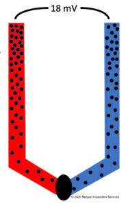 To help explain this, let’s suppose that the voltmeter measures 18 millivolts (mV) between the red and blue ends. Now, looking at a chart for our make-believe thermocouple, we learn that 18 millivolts corresponds to a temperature DIFFERENCE of 500 degrees. If the upper part of the thermocouple (the reference temperature) is at a temperature of 100 degrees, then the fused end would be at a temperature of 600 degrees since we know that there is a 500-degree difference based on the chart.
However, let’s suppose that our thermocouple is in a very cold environment so the reference temperature is 20 degrees below zero. If our voltmeter is still reading 18mV, then that would mean that the measured temperature of the thermocouple is only 480 degrees (500 degrees warmer than the reference temperature of negative 20 degrees). So, it is essential to know the reference temperature that the fused end is being compared to in order to get the actual temperature of whatever is being measured.
Types of thermocouples
There are many different types of thermocouples made from different combinations of pure metals and alloys. Each of these thermocouples has its own specific characteristics and application. Letter designations have been assigned to different thermocouple types to identify them. Types E, J, K, N, & T are “base metal” thermocouples. These base metal thermocouples are the most common types which use iron, constantan (a copper-nickel alloy), nicrosil (alloy of nickel, silicon, chromium, and magnesium), copper, chromel (alloy of nickel and chromium) and alumel (alloy of nickel, aluminum, manganese, and silicon) materials. Type B, R, and S thermocouples are “noble metal” thermocouples (mostly platinum and rhodium). These noble metal thermocouples are more expensive and are used in high-temperature applications.
What does a thermocouple do in a water heater?
As explained in this post, a thermocouple generates voltage when it is exposed to heat. Let me explain how a thermocouple is used in your water heater. It is positioned inside water heaters where it will be within the flame of the pilot light. As long as the pilot light stays lit, the thermocouple will generate an electrical signal which tells the gas control valve on the water heater that the pilot is lit. This signal will keep the gas valve open as long as the pilot flame is still burning. Therefore, this gas valve will continue to supply gas to the pilot light, keeping it burning. This thermocouple will continue sending this signal to the gas control valve day after day and year after year, normally without fail.
Let me explain why this thermocouple is important. I’ll explain this by “removing” the thermocouple from the water heater and allowing the water heater to operate without this important safety feature in place. Let’s suppose that in this theoretical water heater with no thermocouple, the pilot light goes out for some reason. The gas valve will remain open allowing gas to continue to flow. This gas would soon flow out of the water heater and begin filling the home. It would be a serious explosion hazard.
Now, lets look at this same water heater with a thermocouple. When the pilot light goes out for whatever reason, the thermocouple would quickly cool and stop producing an electric signal. This loss of signal would tell the gas valve that the pilot flame is out. This would cause the gas valve to shut which would stop the flow of gas to the water heater. Thus, this thermocouple would prevent gas from flowing into the water heater and into the home. This is the reason that all gas water heaters have a thermocouple in them. Thermocouples are a critical safety component of water heaters.
Why won’t the pilot in my water heater stay lit?
Now that you understand what a thermocouple does in a water heater, it should be easier to understand how a thermocouple can prevent the pilot light in your water heater from staying lit. This problem is likely being caused by a bad thermocouple. If you have a bad thermocouple in your water heater, it will stop sending an electric signal to the gas control valve to keep the gas valve open. Without this electric signal, the gas valve will be shut and the pilot will go out as soon as you let go of the gas override button.
What is the Gas Override Button?
When you light the pilot on a water heater, you must hold down a button on the gas control valve for a few seconds until the thermocouple heats up enough to begin sending the electric signal that will keep the gas valve open. (The red button on the top of the gas control valves in the top two photos below is the gas override button.) This override button allows gas to flow to the pilot light even if the thermocouple is not hot enough. Without this override valve, you would never be able to light the pilot because the you wouldn’t be able to have gas flowing to the pilot without the thermocouple sending its electric signal. And the thermocouple couldn’t send its signal because there would be no flame. You would be caught in a catch 22 situation.
How to test the thermocouple on a water heater?
If the pilot light goes out as soon as you let go of the gas override button, then the cause is most likely a bad thermocouple. It is a fairly simple matter to test the thermocouple in your water heater. You will need a multimeter in order to test it, though.
- Find the gas control valve. Below are pictures of some typical gas control valves.
- Once, you have found the valve, look for a copper wire that attaches to the valve (normally at the bottom). (In all three photos below, the thermostat is the copper wire that connects into the bottom left of the gas valve.) The bottom, right photo shows a new thermocouple.


- Use a small wrench to loosen the connecter that holds the thermostat wire to the gas control valve, and remove the end of the thermostat from the valve.
- Light the pilot and continue to hold the override button to ensure that the pilot stays lit. You may need a helper to do this.
- Set your multimeter to read DC volts. If your multimeter has multiple scales, use the most sensitive scale.
- While your helper holds the override button on the gas valve, hold one probe of the multimeter to the copper wire and the other probe to the tip that you pulled out of the valve. With the pilot’s flame burning, you should get a voltage reading of a few millivolts on the multimeter. If the multimeter continues reading less that about 20 millivolts (mV), then this is an indication that the thermocouple has gone bad. If you get a reading on the multimeter above 20 mV, then the thermocouple is good, and you need to look elsewhere for the problem.
Hopefully, the problem with the water heater pilot is the thermocouple, because it is a cheap and simple process to change out the thermocouple. I will not explain how to do it here. There are a lot of YouTube videos that show you that process from start to finish.
See our blog on Furnace Flame Sensors for more information.
© 2020 Mike Morgan
This article was written by Mike Morgan, the owner of Morgan Inspection Services. Morgan Inspection Services has been providing home, septic and well inspection services throughout the central Texas area since 2002. He can be reached at 325-998-4663 or at mike@morganinspectionservices.com. No article, or portion thereof, may be reproduced or copied without prior written consent of Mike Morgan.